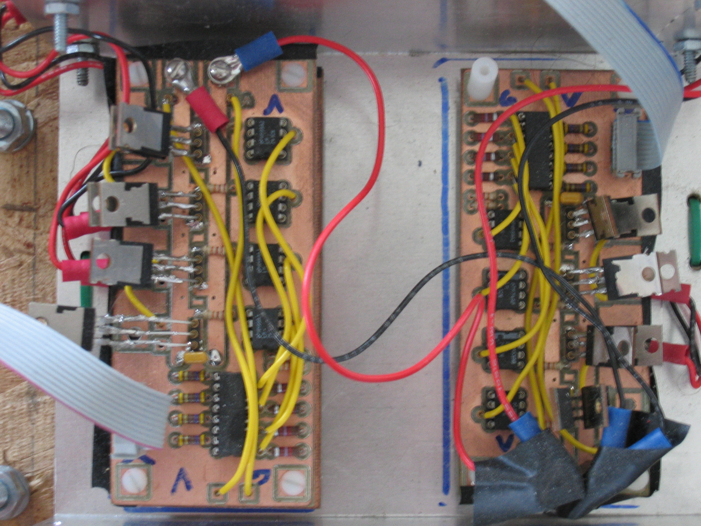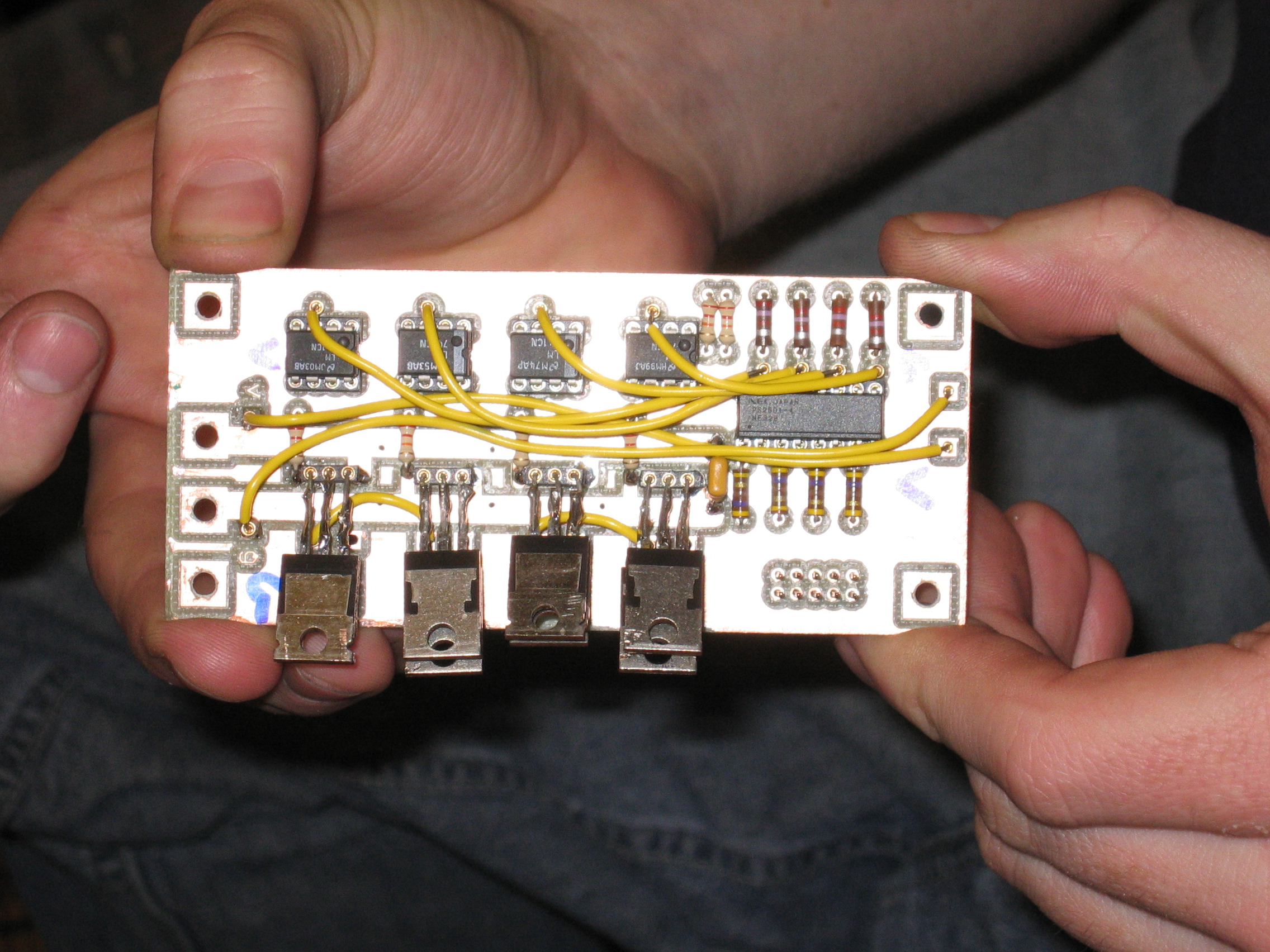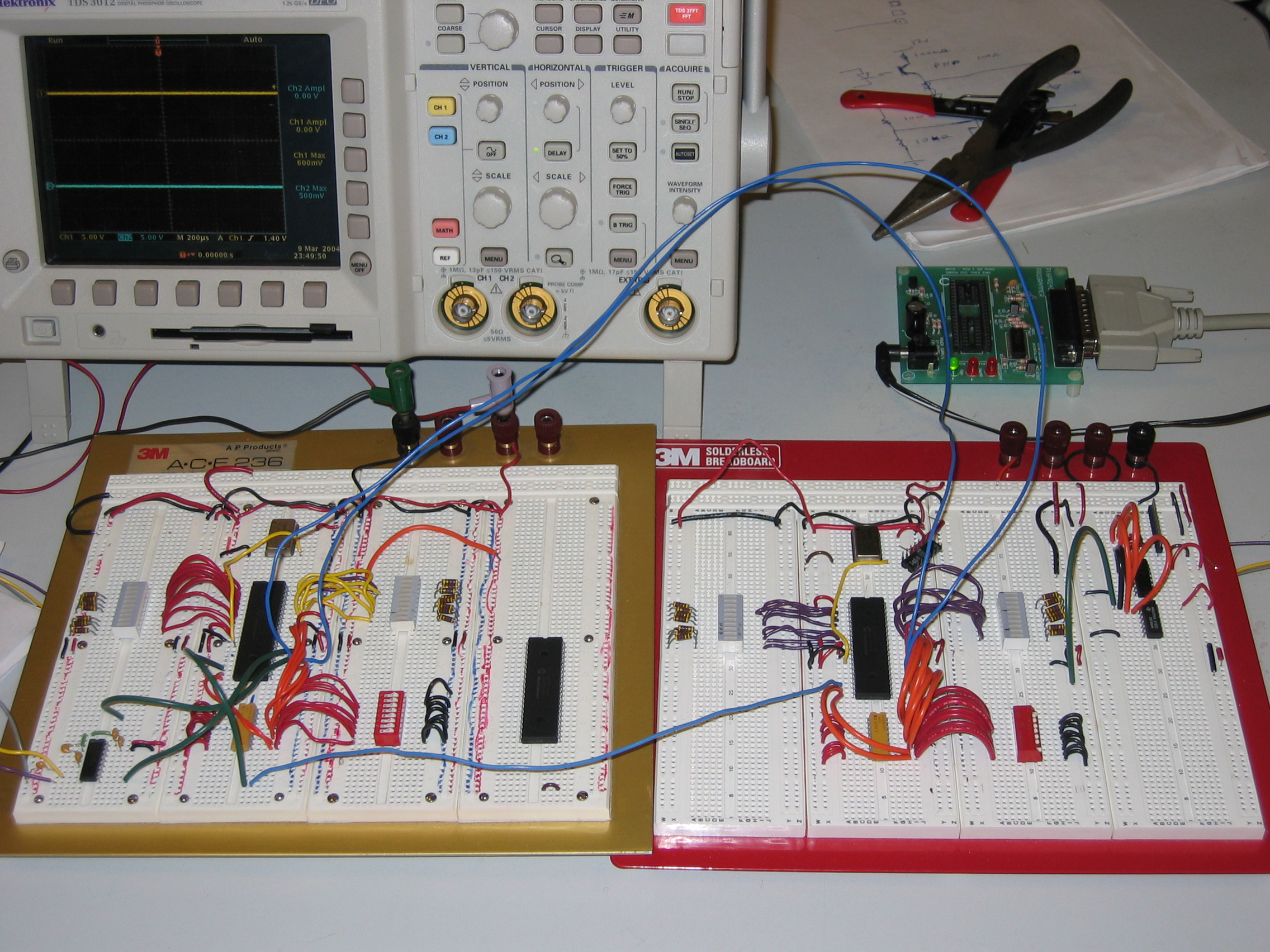
I started working on Zippy in Fall 2003 as part of my analog electronics physics class. Initially Zippy was a tether controlled robot, a switch controller was linked directly to the speed controller. The speed controller consisted of two H-bridges that controlled each motor separately. The N-type and P-type mosfets were salvaged off of old super computer boards (yes we actually pulled parts off old boards) and can handle a max of 6 Amps. A recycled battery was used to power the two 12V motors and 1.5V (double A) batteries were used to power the switch logic. A 3 Amp fuse was used on the 12V battery to stop potential hazards (i.e. fires, exploding mosfets, ect.). As part of the class I added RF transceivers to control Zippy, tethers are just no fun (the RF transmission range was about 50 feet).
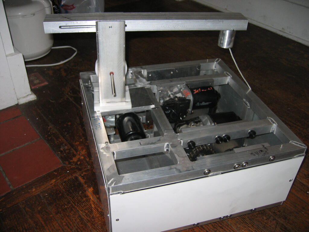
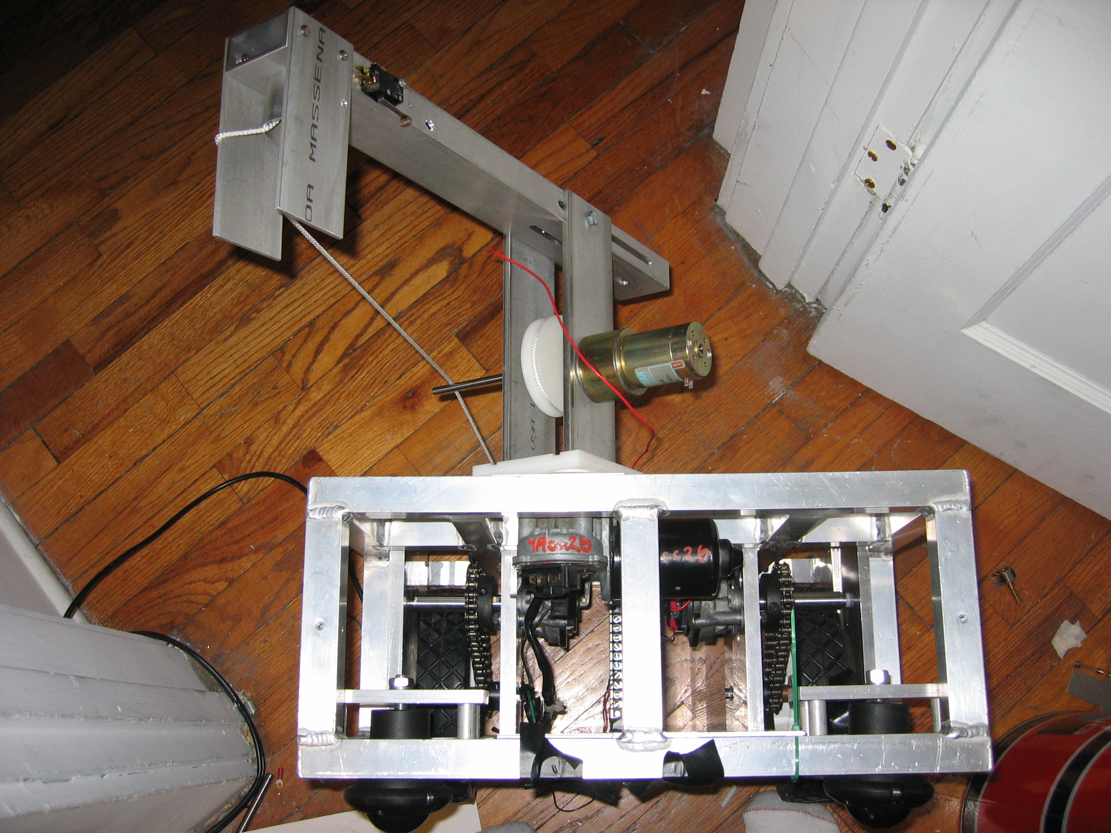
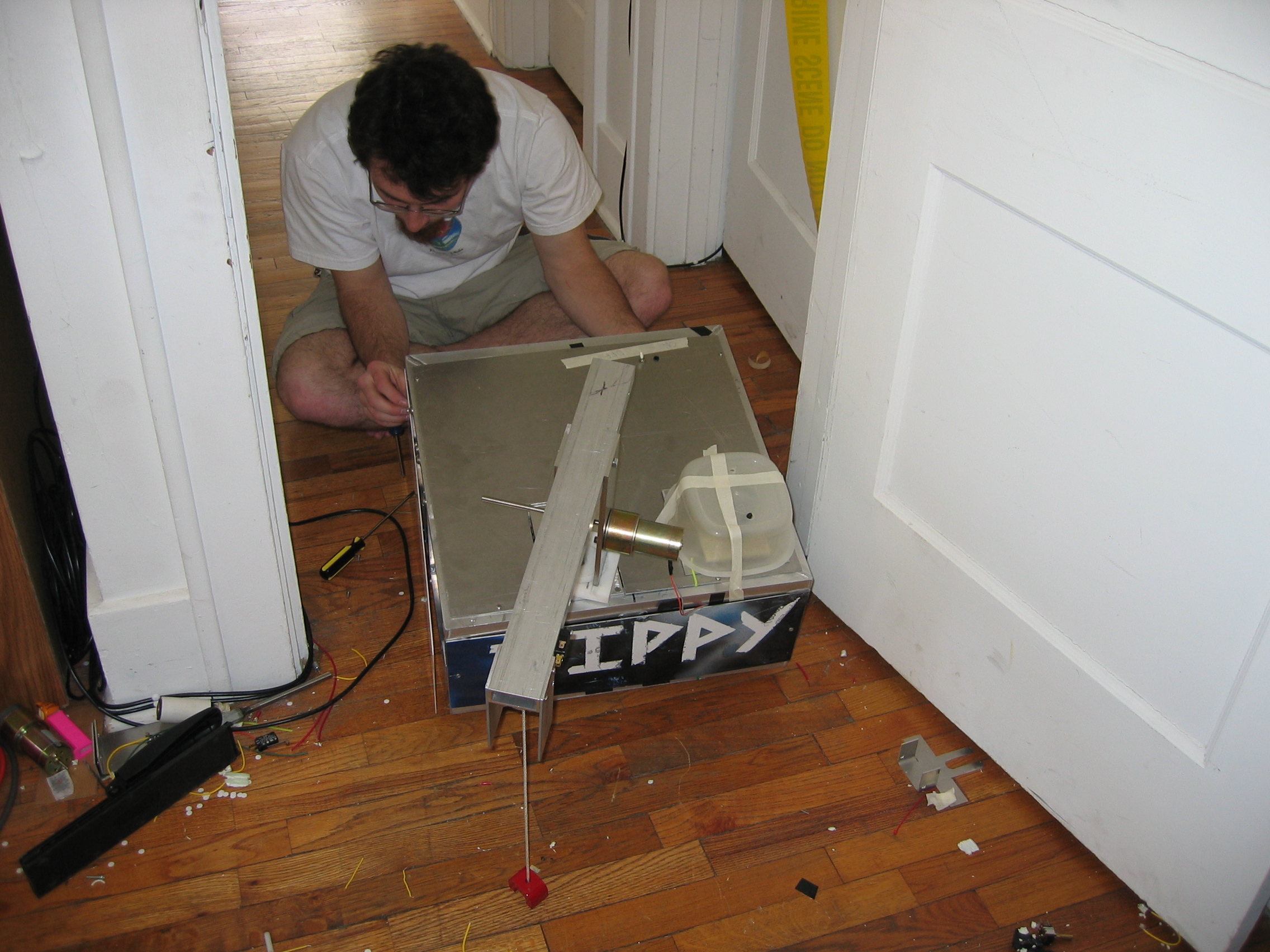
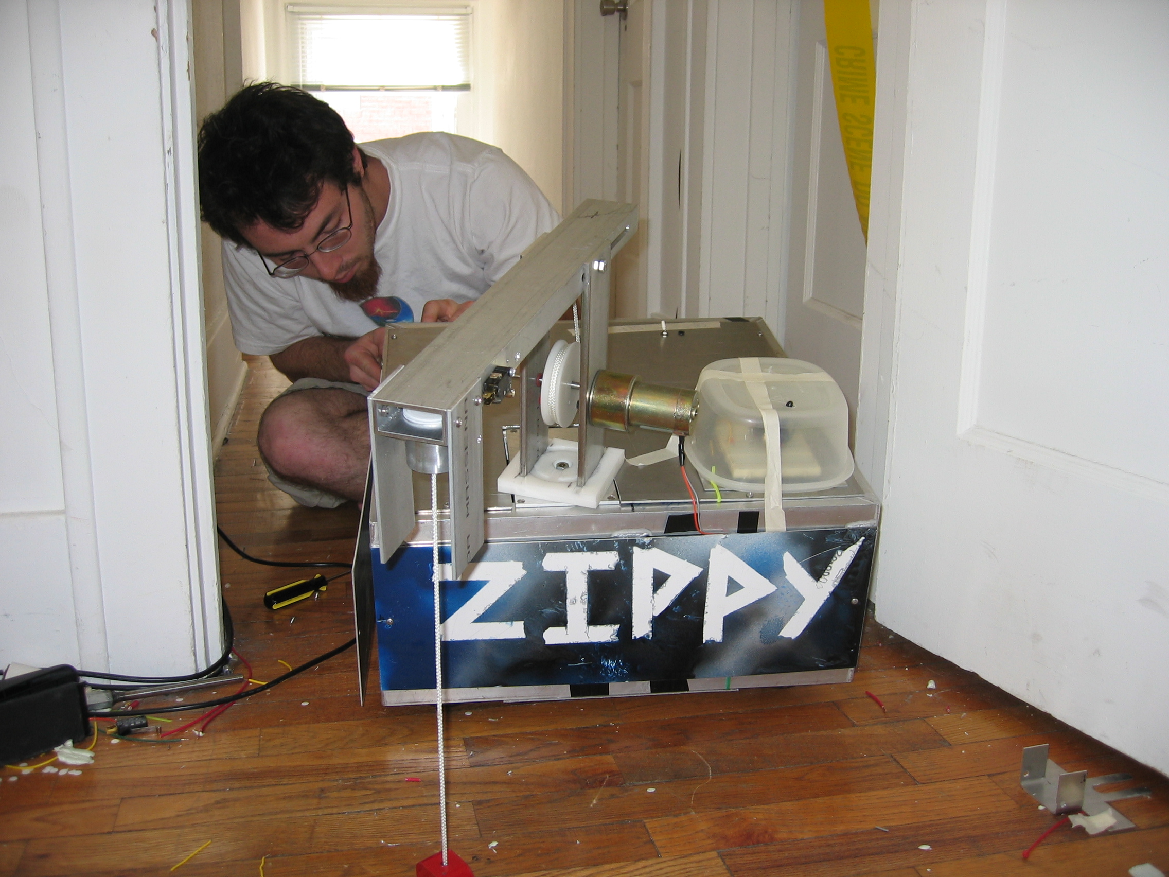
In the spring of 2004, I continued working on Zippy as part of my digital electronics physics class. Zippy was upgraded using 1”square aluminum tubing welded together in to an 18” x 18” x 8” frame. Two drive motors are mounted in the interior to support plates and electrically isolated, typically windshield wiper motors have grounded casings and must be isolated to avoid a short across the frame. A drive gear is attached to each motor and connected by chain to the wheel sprocket. The wheel gear is attached to the wheel axel that drives the two push type lawnmower wheels. A third motor is mounted to the interior topside of the frame which directly drives the arm rotation. A small Pittman motor is used to drive the pulley of arm which raises and lowers the magnet. Zippy was controlled using three H-bridges. The H-bridges used for the finished Zippy are very similar to the ones used in the prototype. High slew rate op-amps were added to limit the amount of time spent in the transition state of the mosfet preventing shoot thru current.
Papers about Zippy:
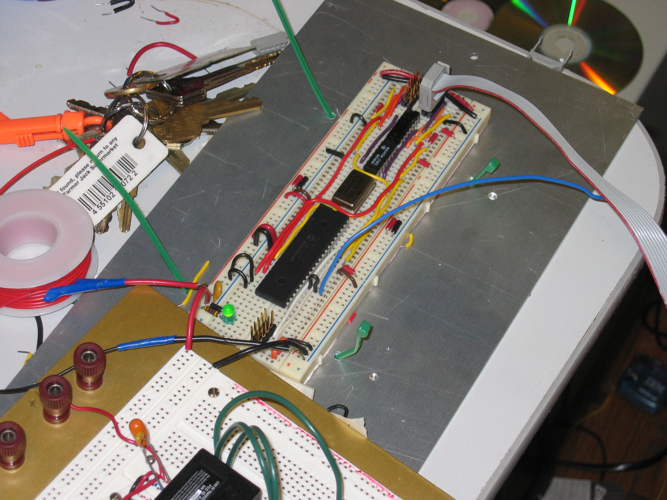
- Digital Communication Using the PIC16F84A Microcontroller
- Wireless Computer Controlled Robotics Using PIC16F77 Microcontroller